


1. Scope of Application
This document outlines the process of transforming robots to ensure that the company's products meet industry standards, maintain stable product quality, and provide guidelines for technical personnel to follow during the transformation process.
Robot automation transformation requires the use of numerous sensors. We suggest utilizing our standard core controller wiring harnesses, TE23 and TE35. This document serves as a guide for operating with the standard wiring harness of the core controller.
Second, Debugging Resources
USB-485/232 Converter

Drive related manual:
CANopen Protocol and Instructions 1.0.pdf
JTSD6030M Description.pdf
Drive Debugging and Parameter Description -v1.1.pdf
Drive configuration software:
easyDRIVE V2.0.rar
Three, Editing, Transformation, and Installation
3. Transformation (chassis driver part)
3.1.1 Installation method for walking motor driver
1. The driver must be securely fixed to the car body. Ensure that the driver is properly connected to the three-phase wire (yellow, U, green, V, blue, W) and the encoder line of the corresponding motor.
2. If the robot is equipped with more than one driver (number ≥2), all CAN_L and CAN_H pins of the slave station can be directly connected. It is recommended to connect them in series, as shown in Figure 3.1.1. If only one communication interface is provided by the driver and the can lines of the driver cannot be connected in series, all can lines of the driver should be drawn out, and all can_H should be pressed into the same Decci cartridge connector, and all can_L should be pressed into the same Decci cartridge connector. Finally, connect the male head of Decci DT06-2S to line 22 and line 23 in TE28 (SRC800V3 can2). (Different SRC800 versions have different can interfaces, so they need to be connected accordingly)
Because some drivers do not provide a cascade port, they can only be connected in series by using wires from the bus, which must be less than 10CM in length.
Note: If there are not enough wiring harnesses required for driver connection during the transformation process, rapid series at the driver end cannot be achieved. The connection mode shown in Figure 3.1.2 can be used, but it is not recommended.

Figure 3.1.1 and Figure 3.1.2
To ensure high-quality communication in CAN networks, it is recommended to install terminal resistance (with a resistance value of 120 ohms) at the farthest drive from the core controller or at the end of the bus. Note that customers can request to purchase matching terminal resistance from the driver manufacturer when purchasing the driver.
3. Method for detecting whether the CAN terminal resistance is correctly open:
Turn off and power down the system. Disconnect the CAN connection cables between the driver and controller (located between Driver4 and controller in FIG. 4.4.1). Utilize a multimeter to measure the resistance between CAN_L and CAN_H on the CAN bus at the driver's side, as illustrated in Figure 4.4.3. If the resistance value is notably less than 120Ω (e.g. 60Ω), there are at least two open terminal resistors.
Disconnect the connection line between Driver1 and Driver2 in FIG. 4.4.1. Utilize a multimeter to gauge the resistance between CAN_L and CAN_H on the CAN bus of Driver1. If the resistance value is 120Ω, it is accurate, as depicted in FIG. 4.4.3. If the resistance value is considerably higher than 120Ω (for instance, a few KΩ), it indicates that the terminal resistance is not open at the end of the CAN bus and necessitates adjustment.

Figure 3.4.3
4. Stop short
Connect all drivers' D1 to the driver's 24V. Connect all drivers' DIRENT in parallel to SRC2000 emergency stop and output 1+ (Line TE354), and connect the other emergency stop output 1- (line TE355) to 0V.
Four, Drive Parameter Configuration
Tools:
USB to RS-485/RS-232 Converter

Drive related manual:
CANopen Protocol and Instructions 1.0.pdf
JTSD6030M Description.pdf
Drive Debugging and Parameter Description -v1.1.pdf
Drive configuration software:
easyDRIVE V2.0.rar
1. Connect your computer to your drive using a USB-485/232 converter.
1. Launch the software and import the parameter file
Debugging software can be used without installation. Once you have located the software executable file, double-click on the "easyDrive.exe" icon to open the software. 
On the import parameter interface, click the "Import" button and select the "easyDriveParamXXXX.xml" parameter file to open. 
Establishing a communication connection
The driver and host computer communicate with each other through RS232/RS485 asynchronous serial communication, using the MODBUS-RTU protocol. Connect the RS485 cable to the driver and the other end to the USB port on the PC.
On the "Communications" page, click "Serial Scan" to automatically identify the COM port to the communications cable, and then click "Connect" to connect to the driver. Once connected, you can view the model and software version of the driver. The status bar at the lower right of the page displays the "State". 
The driver supports three Baudrates: 9600, 19200, and 38400. The factory default is 9600 BPS.
2. easyDRIVE Motor Parameter Setting
Step 1: Set Motor Parameters
The main parameters that need to be set are "Motor Type", "Motor Rated Speed", "Motor Rated Current", "Motor Overload Ratio", and "Motor Pole Number (Pole/2)". Refer to the motor manual and enter these parameters into the designated red box. Press "Enter" after each parameter.
For encoder settings, take the common 2500-line incremental encoder servo motor as an example. Select "Inc+HALLRecoder" for "Encoder Type" and "2500" for "Incremental Resolution". Do not fill in other parameters at this time. After completion, click "Save Setting Parameters". 
Step 2: Motor Self-Learning
If the motor is unfamiliar or its parameters are unknown, and the motor power line phase sequence and Hall signal are also unknown, the motor self-learning function can be used to automatically adapt the drive and motor.
Before starting the self-learning of motor parameters, accurately fill in the motor's configuration parameters and save them. The drive needs to be powered on again, and then the self-learning function can be started. Click the "Enable Self-Learning" button to enter the self-learning state automatically.
Steps for motor self-learning:
8) The motor should be in a no-load or light load state. Too much load will cause deviation in learning parameters and affect motor operation.
9) Ensure that the motor encoder (including Hall signal) is correctly connected to the motor power line.
10) Set the motor type, motor rated current, motor rated speed, encoder type, and other parameters correctly and save them.
11) Click "Start self-learning". The motor will automatically select low speed, and the self-learning status light will turn green.
12) Wait until the self-learning status light turns red and the self-learning is complete.
After completing the above steps, the motor parameter learning is finished. After writing the parameters into the drive, power off and restart.
3. Configure CAN communication
Configure the canID and baud rate as necessary, and enable CAN communication.
3. Save the motor parameters, power on, and restart the machine.

5. Robot Model Configuration Instructions
Note: These parameters should be filled in according to the actual conditions of the driver, motor, and reducer selected;
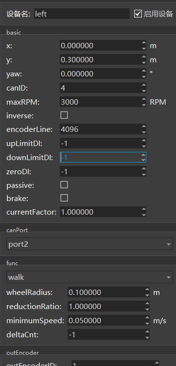
****
Note: The deceleration ratio, number of encoder lines, maximum motor speed, and driver brand should be filled in according to the actual selection.
Six, Drive Function Detection
1. Prior to installing the shell after vehicle assembly, double-check the cables to ensure proper connection.
2. Elevate the car body to raise the wheels off the ground. Activate the robot and connect it to a network cable. Utilize Roboshop software to control the robot and set the wheels in motion. Employ the CanScope clip to detect CAN messages on the CAN bus for a minimum of 1 hour. The CAN messages are devoid of errors.
Step 3: Place the car body on the ground and utilize the Roboshop software to control the robot's movements, including forward, backward, left, and right.
4. Prior to pressing the emergency stop button, attempt to push the robot. If it does not move (motor is disabled), verify that the Roboshop robot is in the "No Emergency Stop" and "Drive No Emergency Stop" state, as depicted in Figure 6.1. Once the emergency stop button has been activated, push the robot again to enable the motor and ensure that it is now in the "Emergency Stop" and "Drive Emergency Stop" state in Roboshop, as illustrated in Figure 6.2.
5. Test the communication between the driver and the controller by using the Roboshop software to operate the robot and move it forward. During the movement process, unplug the canH and canL connections between the driver and the controller.

Figure 6.1:

Figure 6.2:
Perform a 24-hour task chain motion aging test and check the Robokit Log for any error alarms.
Vii. Supplementary Material
7.1 Usage of the USB CAN card
1. Software Installation - Install the USB_CAN Tool software (Contact the CAN card vendor for software and user manuals).
2. Hardware Connection - Acquire a USB CAN card and cables, then connect the CAN_H cable to the SRC2000 external wiring harness TE35 33, and connect the CAN_L cable to the SRC2000 external wiring harness TE35 32. Refer to Figure 7.1.1:

Figure 7.1.1:
3. Open the USB CAN tool, select [Device Operation (O)] and then select [Start Device (S)]. Confirm the CAN parameters, setting the [baud rate] to 250Kbps and selecting [CAN channel number] as channel 1. Finally, click [Confirm]. Refer to Figure 7.1.2 for details.

Figure 7.1.2:
4. Choose "Display (V)" and uncheck "Merge same ID data (M)". The CAN message is displayed in Figure 7.1.3.
 Figure 7.1.3:
7.2 Usage of udpconsole
udpConsole is a handy tool utilized by our engineers for debugging purposes. It allows you to review the error information reported by the firmware.
1. Prior to launching the udpconsole tool, ensure that the computer is physically linked to the robot via a network cable.
2. Launch udpconsole to test the driver functionality and verify the displayed content on udpconsole.
Error frames may occur during driver communication, as illustrated in Figure 7.2.1:

Figure 7.2.1
Figure 7.2.1 - Enhanced visualization of data.
Common Error Codes for Drives
The alarm can be detected through the driver's indicator light. The indicator light on the driver panel displays the fault code of the driver. Additionally, the service driver will automatically stop the motor and cut off the enable signal of the motor in case of a fault alarm. Users should identify the cause of the failure and troubleshoot it.


 Thanks feedback
 Thanks feedback
 Build your own AMR fleet within days


