


1. Scope of Application
This document outlines the process of transforming robots to ensure that the company's products meet industry standards, maintain stable product quality, and provide guidelines for technical personnel to follow during the transformation process.
Robot automation transformation requires the use of numerous sensors. We suggest utilizing our standard core controller wiring harnesses, TE23 and TE35. This document serves as a guide for operating with the standard wiring harness of the core controller.
Second, Debugging Resources
USB-485 Converter

Drive related manual:
ZLAC8030L CANopen communication routine Version 1.00.pdf
ZLAC8030L RS485 communication routine Version 1.00.pdf
ZLAC8030L Servo Hub Driver User Manual Version 1.00.pdf
Drive configuration software:
ZLTECH upper computer software and driver.zip
Three, Editing, Transformation, and Installation
3. Transformation (chassis driver part)
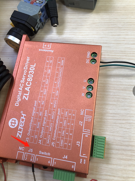
3.1.1 Installation method for walking motor driver
1. The driver must be securely fixed to the car body. Ensure that the
driver is properly connected to the three-phase wire
(yellow, U, green, V, blue, W)
and the encoder line of the corresponding motor.
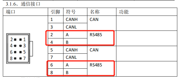
2. If the robot is equipped with more than one driver (number ≥2), all
CAN_L and CAN_H pins of the slave station can be directly connected. It
is recommended to connect them in series, as shown in Figure 3.1.1. If
only one communication interface is provided by the driver and the can
lines of the driver cannot be connected in series, all can lines of the
driver should be drawn out, and all can_H should be pressed into the same
Decci cartridge connector, and all can_L should be pressed into the same
Decci cartridge connector. Finally, connect the male head of Decci DT06-2S
to line 22 and line 23 in TE28 (SRC800V3 can2).
(Different SRC800 versions have different can interfaces, so they need
to be connected according to the specific SRC800 version)
As some drivers lack a cascade port, they can only be connected in series by using wires from the bus, which must be shorter than 10CM.
Note: If there are not enough wiring harnesses required for driver connection during the transformation process, rapid series at the driver end cannot be achieved. The connection mode shown in Figure 3.1.2 can be used, but it is not recommended.

Figure 3.1.1 and Figure 3.1.2
To ensure high-quality communication in a CAN network, it is recommended to install a terminal resistance (with a resistance value of 120 ohms) at the farthest drive from the core controller or at the end of the bus. Please note that customers can request to purchase matching terminal resistance from the driver manufacturer when purchasing the driver.
3. Method for detecting whether the CAN terminal resistance is correctly open:
Turn off and power down the system. Disconnect the CAN connection cables between the driver and controller (located between Driver4 and controller in FIG. 4.4.1). Utilize a multimeter to measure the resistance between CAN_L and CAN_H on the CAN bus at the driver's side, as illustrated in Figure 4.4.3. If the resistance value is notably less than 120Ω (e.g. 60Ω), there are at least two open terminal resistors.
Disconnect the connection line between Driver1 and Driver2 in FIG. 4.4.1. Utilize a multimeter to gauge the resistance between CAN_L and CAN_H on the CAN bus of Driver1. If the resistance value is 120Ω, it is accurate, as depicted in FIG. 4.4.3. If the resistance value is considerably higher than 120Ω (for instance, a few KΩ), it indicates that the terminal resistance is not open at the end of the CAN bus and necessitates adjustment.

Figure 3.4.3
4. Stop short
Connect all driver
J4-INPUT1
ports
to
J3-5V
. Connect all
J4-ICOM ports
of the driver in parallel to
SRC2000 emergency stop transmission 1+
(Line TE354), and connect the other
emergency stop output 1-
(line TE355) to the
J3-GND port
of the driver.

Four, Drive Parameter Configuration
Tools:
USB to RS-485 converter

Drive related manual:
ZLAC8030L CANopen communication routine Version 1.00.pdf
ZLAC8030L RS485 communication routine Version 1.00.pdf
ZLAC8030L Servo Hub Driver User Manual Version 1.00.pdf
Drive configuration software:
ZLTECH upper computer software and driver.zip
1. Connect your computer to your drive using a USB-485 converter.
2. If the driver firmware needs to be updated for the emergency stop function,
run the driver firmware upgrade software
Zlac-serv-bin-v2.0.zip

Firmware information:
80300000-V1-0-20K-22302-NewAPP-20227029.zip
(Decompress it into a BIN file and use it)
Upgrade the firmware according to the operation document.
ZLAC-SERVO-BIN-V2.0 Firmware update description.docx
(Upgrade fails or does not work smoothly with the supplier)
3. Launch the drive configuration software, choose the appropriate port
number, and click to establish a connection with the serial port.


4. Adjust the drive ID and baud rate as needed, select Speed control mode
as the working mode, and save the parameters to the drive.

5. Adjust the parameters and
turn on the driver
to activate the changes.
6. The
driver terminal resistor must be connected
in order to establish communication.
7. Set the offline protection time for communication between the driver
and controller. Connect the USB CAN box to the middle Diamond drive (drive
connector 1 is CAN_H, 3 is CAN_L), and ensure that it is connected according
to the CAN baud rate set on the upper computer beforehand (if the configuration
of the Middle Diamond drive has not been modified, the default baud rate
of the Middle Diamond drive is 500kbps).
Note: The CAN channel of the USB CAN box requires a resistance of 120
Ohm


8. After connecting the USB CAN box, enter the frame ID based on the drive ID (for example: if the drive ID is set to 4, the frame ID is 00 00 60 04 ), and set the communication outage time to 2000h (usually set to 200ms, so the send message information is 2B 00 2000 C8 00 00 00 , note that C8 is the set time converted into hexadecimal ). If the drive returns 60 00 20 00 00 00 00 00, the setting is successful.

9. Modify the emergency stop mode of input1 port to disable after emergency
stop. Enter the frame Id based on the drive ID (for example: If the drive
ID is set to 4, the frame ID is
00 00 60 04
). Send packet
2B 2F 20 03 01 00 00 00
and receive packet
60 2F 20 03 00 00 00
to confirm the successful modification.

10. Turn off the power and restart the drive once the modification is complete.
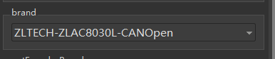
5. Robot Model Configuration Instructions
The walking motor's parameters were configured based on the actual motor and deceleration conditions. The brand is ZLTECH-ZLAC8030L-CANOpen.
Note: These parameters should be filled in according to the actual conditions of the driver, motor, and reducer selected;
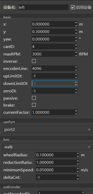
****
Note: The deceleration ratio, number of encoder lines, maximum motor speed, and driver brand should be filled in according to the actual selection.
Six, Drive Function Detection
1. Prior to installing the shell after vehicle assembly, double-check the cables to ensure proper connection.
2. Elevate the car body to raise the wheels off the ground. Activate the robot and connect it to a network cable. Utilize Roboshop software to control the robot and set the wheels in motion. Employ the CanScope clip to detect CAN messages on the CAN bus for a minimum of 1 hour. The CAN messages are devoid of errors.
Step 3: Place the car body on the ground and utilize the Roboshop software to control the robot's movements, including forward, backward, left, and right.
4. Prior to pressing the emergency stop button, attempt to push the robot. If it does not move (motor is disabled), verify that the Roboshop robot is in the "No Emergency Stop" and "Drive No Emergency Stop" state, as depicted in Figure 6.1. Once the emergency stop button has been activated, push the robot again to enable the motor and ensure that it is now in the "Emergency Stop" and "Drive Emergency Stop" state in Roboshop, as illustrated in Figure 6.2.
5. Test the communication between the driver and the controller by using the Roboshop software to operate the robot and move it forward. During the movement process, unplug the canH and canL connections between the driver and the controller.

Figure 6.1:

Figure 6.2:
Perform a 24-hour task chain motion aging test and check the Robokit Log for any error alarms.
Vii. Supplementary Material
7.1 Usage of the USB CAN card
1. Software Installation - Install the USB_CAN Tool software (Contact the CAN card vendor for software and user manuals).
2. Hardware Connection - Acquire a USB CAN card and cables, then connect the CAN_H cable to the SRC2000 external wiring harness TE35 33, and connect the CAN_L cable to the SRC2000 external wiring harness TE35 32. Refer to Figure 7.1.1:

Figure 7.1.1:
3. Open the USB CAN tool, select [Device Operation (O)] and then select [Start Device (S)]. Confirm the CAN parameters, setting the [baud rate] to 250Kbps and selecting [CAN channel number] as channel 1. Finally, click [Confirm]. Refer to Figure 7.1.2 for details.

Figure 7.1.2:
4. Choose "Display (V)" and uncheck "Merge same ID data (M)". The CAN message is displayed in Figure 7.1.3.
 Figure 7.1.3:
7.2 Usage of udpconsole
udpConsole is a handy tool utilized by our engineers for debugging purposes. It allows you to review the error information reported by the firmware.
1. Prior to launching the udpconsole tool, ensure that the computer is physically linked to the robot via a network cable.
2. Launch udpconsole to test the driver functionality and verify the displayed content on udpconsole.
Error frames may occur during driver communication, as illustrated in Figure 7.2.1:

Figure 7.2.1
Figure 7.2.1 - Enhanced visualization of data.
Common Error Codes for Drives
The green LED serves as the power indicator. It remains steadily lit when the driver is powered on and goes out when the power is cut off. The red LED, on the other hand, acts as the fault indicator. In case of a driver failure, the LED will stop flashing and display the corresponding fault code. To clear the alarm, the user needs to use the software to rectify the fault.


For instance, this motor detects errors bit by bit. For example:
1.0x81 error indicates an overvoltage error, which can be analyzed using
the table information.
2.0x8 error indicates an overload.
3.8080 error refers to a voltage error.
9. Appendix
9.1 Driver Wiring Diagram


9.2 Drive


 Thanks feedback
 Thanks feedback
 Build your own AMR fleet within days


