


1. Scope of Application
This document is intended for the SSH-10-sensor method of configuring range sensors.
1.1 SSH-10-sensor Distance Sensor Structure
Standard Edition 1.1.1
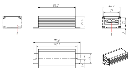
Figure 1-1: Product Dimensions Figure 1-PORT 2: Power Indicator
1.1.2 Ethernet Version
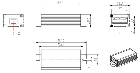
Figure 1-2: Product Dimensions. Figure 1-PORT 2: Power Indicator. 3-RJ45 Ethernet Port.
The power indicator remains green and steady during regular operation.
1.2 Nameplate
To Be Determined
Second, Debugging Resources
Instruction manual for North Wake Sensor:
Instruction manual for SJ-PM-TFmini Plus A05.pdf
SSH-10Agreement Description:
Serial Port Assistant:
Commonly used USB to serial driver (upon request):
Recommended USB driver installation tool setup
Download FTDI232 Windows Driver Version 212226
USB Turn 485 Tools:
USB to 485 A meets SSH-10 AUSB to 485 B junction of SSH-10 B
III. Instructions for Electrical Wiring
3.1 Port
PORT is primarily utilized for powering, uplink communication, and connecting sensors to the sensor concentrator.
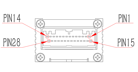
Figure 3-1: PORT Appearance
PIN1 | ID1_RX | PIN15 | GND |
PIN2 | ID1_TX | PIN16 | ID1_5V |
PIN3 | ID2_TX(a) | PIN17 | GND |
PIN4 | ID2_RX(a) | PIN18 | ID2_5V |
PIN5 | ID3_RX | PIN19 | GND |
PIN6 | ID3_TX | PIN20 | ID3_5V |
PIN7 | ID4_RX | PIN21 | GND |
PIN8 | ID4_TX | PIN22 | ID4_5V |
PIN9 | ID5_RX | PIN23 | GND |
PIN10 | ID5_TX | PIN24 | ID5_5V |
PIN11 | RS485_A | PIN25 | GND |
PIN12 | RS485_B | PIN26 | 24V_INPUT |
PIN13 | CAN_H(b) | PIN27 | GND |
PIN14 | CAN_L(b) | PIN28 | 24V_INPUT |
Table 2-1: Port Pin Definitions
Attention:
(a) The definition of TX and RX for PIN3 and 4 differs from that of other sensors. |
|---|
(b) In batch 01 and subsequent batches, CAN_H is in PIN13 and CAN_L is in PIN14. RS485 is only in lot 00. |
(c) Cross-connect the PIN1-10 communication cable. Connect the RX of the North wake sensor to the TX of SSH-10, and connect the TX of the North wake sensor to the RX of SSH-10. TXRX here refers to the definition of SSH-10. |
(d) The ID in the table corresponds to the device ID of the North wake, which should be connected starting from 1 and increasing in sequence. |
3.1.1 Power Supply
Power Input Requirements: The voltage range should be 24VDC with a tolerance of ±5%, and the power supply capacity must be 0.4A or greater.
Ensure that abnormal power inputs, such as reverse polarity and overvoltage, are not allowed, as this may result in the concentrator becoming abnormal or damaged.
The power cable's diameter must meet the maximum current requirement of the power supply. It is recommended to use a diameter larger than 0.5 square mm.
Positive Terminal | Negative Terminal |
|---|---|
PIN26, 28 | PIN25, 27 |
Table 3-2: Power Cables for the Port
3.1.2 Uplink Communication
RS485 Communication: Upload sensor data. By default, there is no terminal resistance. External 120 ohm resistance should be connected as required. To ensure communication quality, it is recommended to use the characteristic impedance of 120 ohms twisted pair cable or RS485 bus-specific cable. Table 2-3 provides definitions.
A | B | Shared Point |
|---|---|---|
PIN11 | PIN12 | Negative power supply PIN25,27 |
Table 3-3: Definitions of PORT RS485
CAN Communication: Upload sensor data. By default, there is no terminal resistance. External 120 ohm resistance should be connected as required. To ensure communication quality, it is recommended to use 120 ohm twisted pair cable or CAN bus dedicated cable. Table 2-4 provides definitions:
CAN_H (a) | CAN_L (a) | Common Ground |
|---|---|---|
PIN13 | PIN14 | Negative power supply connected to PIN25 and PIN27 |
Table 3-4: Definitions of RS485 PORT
(a) In batch 01 and later batches, PIN13 is labeled as CAN_H, while PIN14 is labeled as CAN_L. Only in batch 00 is it labeled as RS485.
3.1.3 Sensor
This code is used for communication with the North Wake Sensor TFmini Plus in a concentrator. The North Wake Sensor uses TTL UART communication and does not have a separate ID. The only way to differentiate between sensors is by their wiring position on the concentrator. Wiring starts at PIN1 and increases sequentially.
Positive 5V Power Supply | Negative Power Terminal GND | TX | RX | |
|---|---|---|---|---|
ID1 | PIN16 | PIN15 | PIN2 | PIN1 |
ID2 | PIN18 | PIN17 | PIN3(a) | PIN4(a) |
ID3 | PIN20 | PIN19 | PIN6 | PIN5 |
ID4 | PIN22 | PIN21 | PIN8 | PIN7 |
ID5 | PIN24 | PIN23 | PIN10 | PIN9 |
Table 3-5: Cable Connections for PORT Sensors
(a) The definition of TX and RX for PIN3 and 4 differs from that of other sensors. |
|---|
(b) Communication lines must be cross-connected, with the |
3.1.3 Connecting Cables
The PORT is a male pin connector. The corresponding female plug and pin types are as follows. Typically, there is one female plug and 28 pins:
Figure 3-2:
This section provides an example of how to connect sensors and concentrators using ID1.
Definition of Concentrator | North Wake Sensor | |||
|---|---|---|---|---|
PIN1 | ID1_RX | <-> | TXD | PIN3 |
PIN2 | ID1_TX | <-> | RXD | PIN2 |
PIN15 | GND | <-> | GND | PIN4 |
PIN16 | ID1_5V | <-> | +5V | PIN1 |
Table 3-6: Reference Cable Connections for PORT Sensors
Note: To establish communication, cross-connect the communication lines. Connect the RX of North Wake Up to the TX of SSH-10, and connect the TX of North Wake Up to the RX of SSH-10. Connect the communication lines in sequence starting from 1, without skipping any. The attached North Wake Sensor TFmini Plus should follow the same line sequence: |
|---|
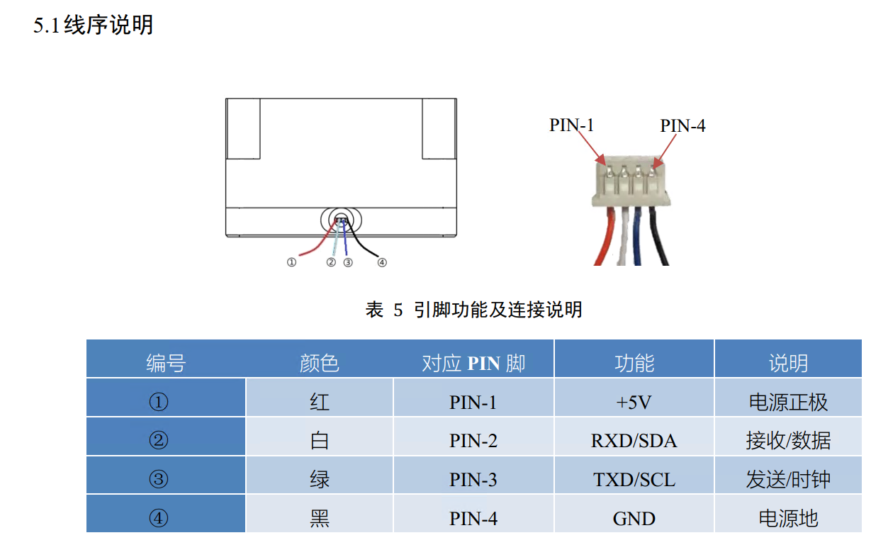
Sequence Definition of the North Wake Sensor, Figure 3-3
3.2 Ethernet (Optional)
The concentrator is equipped with one RJ45 Ethernet port that supports standard 100 Mbit/s, specifically 100BASE-TX. The RS485 port can also be used for upstream connections. We recommend using CAT5E or higher network cables.
This feature is optional.
Four, Model Configuration
4.1 General Configuration
Model file ID: starts from 1 and increases in sequence without skipping. SSH-10 It should be wired in order, starting from PIN1 and not skipping any pins.
4.2 SRC2000 Configuration Method
Company ID:
comID 5 corresponds to [485 Communication 4 (default configuration, not mixed)]
ComID 4 corresponds to [485 Communication 3]
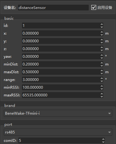
Figure 4-1: Software Configuration
Keyword | Description | Value | Unit |
|---|---|---|---|
x | X-axis Position | The position of x in the right-hand coordinate system, as in the car model | m |
y | Y-axis Position | The position of y in the right-hand coordinate system, as in the car model | m |
z | Z-axis Position | The position of z in the right-hand coordinate system, as in the car model | m |
yaw | Mounting Angle | The angle of direction in the right-handed coordinate system, as in the car model | ° |
minDist | Minimum Detection Distance | The minimum detection distance of the distance sensor, expressed in meters. The minimum distance can be obtained by checking the distance sensor instruction manual | m |
maxDist | Maximum Detection Distance | The maximum detection distance of the distance sensor, expressed in meters. The maximum distance can be obtained by checking the distance sensor instruction manual | m |
range | Receiving Half Angle | The X receiving half angle of the distance sensor (the angle of scatter transmitted by the radar), in degrees. This information can be obtained by checking the distance sensor instruction manual | ° |
minRSSI | Minimum Signal Strength | The minimum signal strength of the distance sensor. The distance sensor number is only valid within a certain range of signal strength. The minimum signal strength can be obtained by checking the distance sensor instruction manual | |
maxRSSI | Maximum Signal Strength | The maximum signal strength of the distance sensor. The distance sensor number is only valid within a certain range of signal strength. The maximum signal strength can be obtained by checking the distance sensor instruction manual | |
brand | Brand Name | Select the appropriate brand |

Figure 4-2: Recommended connection to SRC2000
4.3 SRC800/SRC3000 Configuration Method:
Device Name: Serial Port Number. The value can be configured based on the cable connection.
Key | Description | Value | Unit |
|---|---|---|---|
Port | The port number used for the connection. | ||
DevName | The name of the device being connected to. |
5. Simple test instructions
5.1 Verify Power Supply to the North Awakens
Use your mobile phone camera to observe the transmitter surface of Beixing. If the power supply is functioning properly, the transmitter light can be observed through the camera.

Figure 5-1: The sensor is functioning correctly.
5.2 Explanation of Roboshop Error:
5.2.1 SSH-10 No data is Uploaded
Possible reasons:
Error52959 |
|---|
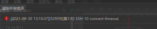
5.2.2 The Northwake Connection Times Out
In this scenario, SSH-10 functions properly, whether it is a single or multiple occurrence. However, North wake up may experience irregularities, as depicted in the following illustration. Specifically, ID 1 may encounter a North wake up timeout.
Error52959 |
|---|

5.2.3 Receiving Incorrect Data
Restart SSH-10
Received Incorrect Data from SSH-10 |
|---|
5.3 Packet Examples
Use the USB to 485 module to connect to SSH-10 for the 485 connection. This can be viewed through the serial port assistant for North wake up. The baud rate is 115200.
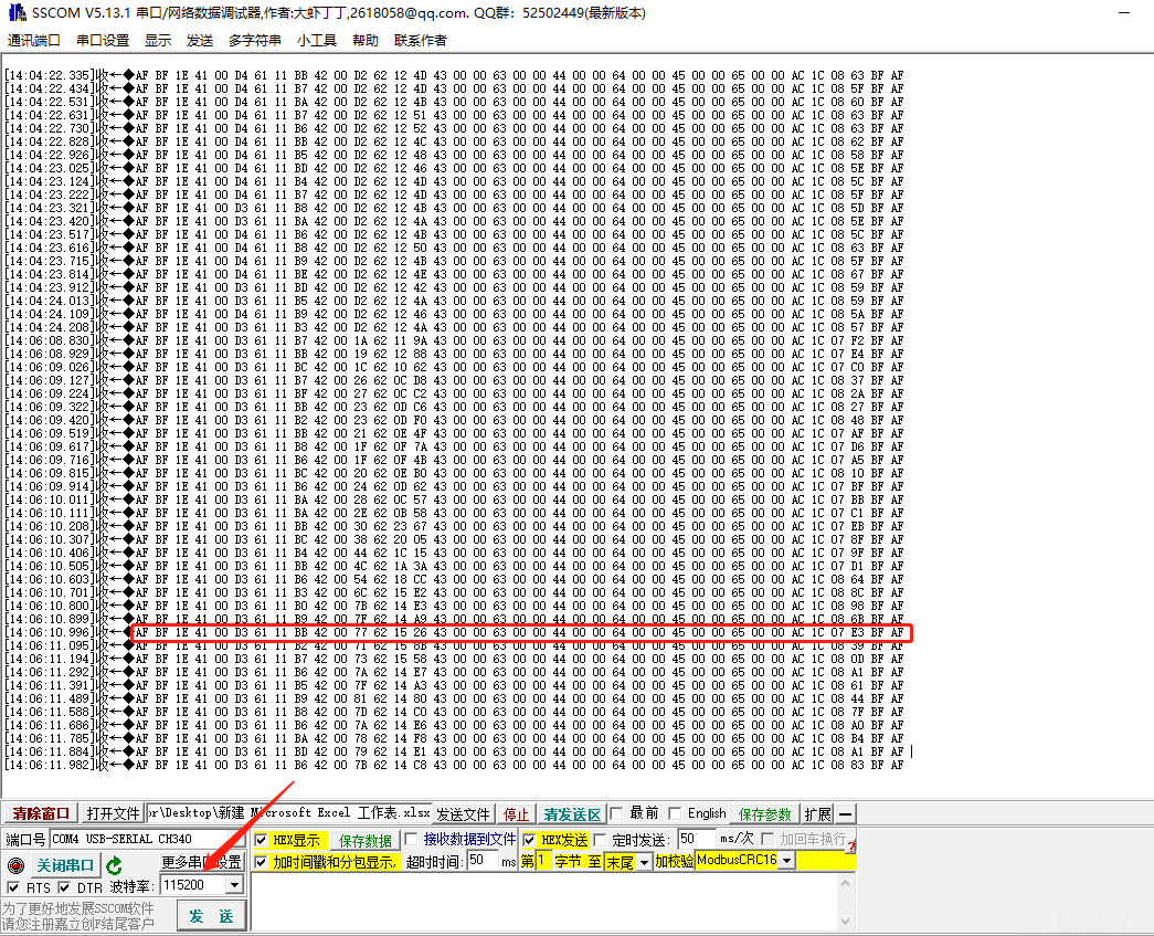
Example 1 of packet from host computer - Figure 5-2
5.3.1 Description of Packets
Frame Header: AF BF
End of frame: BF AF
Simply divide the data into 5 areas corresponding to 5North Wake Sensors, which are distinguished by ID numbers ranging from 41 to 45.
Example: 4100D36111B6
Identification Number: 1
Distance: 00 D3
Signal Strength: 11 B6
Acquired some North Wake Sensor. The data area corresponding to it will undergo changes, allowing you to determine whether the sensor connection is normal. Adjusting the [timeout] can align the data reception.

Example 2 of Packet in Upper Computer - Figure 5-3
VI. Frequently Asked Questions
Q: Some parts of the sensor have data, while others do not?
A: Firstly, check the connection and ensure that the connection definition is correct and the connection is secure. Abnormal connections may include short circuits, open circuits, virtual connections, cable harness shell damage, connector shell damage, and more. Next, consider replacing the sensor suspected of damage. If the fault is eliminated, it is likely that the sensor was damaged.
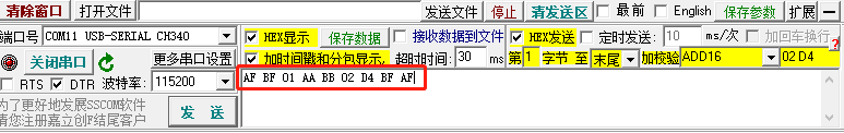
Q: SSH-10 The working indicator is blinking, but no message is being uploaded.
A: Make sure the connection is correct and use the serial port assistant to send AF BF 01 AA BB 02 D4 BF AF. If a return packet is received (with the same packet format as above), it indicates that the SSH-10 firmware is in query mode and needs to be rewritten.


 Thanks feedback
 Thanks feedback
 Build your own AMR fleet within days


