


Premise:
Please do not modify the HTML tags and attributes. Simply refine the text within the following HTML code:Premise:
Before debugging, please carefully read the PGV QR code.
1. Scope of Application
1.1 Models that are Applicable
MV-R3051MG010, R3138MG010
MV-R3051MG010, R3138MG010
1.2 Power Supply
24 volts
1.3 QR Code Types Supported
DM12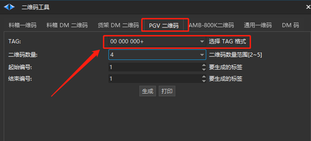
1.4 Code Reading Camera version:

1.5 Scope of work
From 20mm to 100mm and above
1.6 Firmware:
The underlying SRC firmware is version 2.0.34 or newer.
Two, Dahua Reading Camera Debugging Resources
Code Reader Camera User Manual:
Chinese Dahua AGV Reader User manual V0.0.9-20210224144035.pdf
Chinese HuARui 3000 series AGV reader R3138MG010 product single page
Code reading, camera debugging, upper computer:
SVStudio Setup 2.1.0 20190809.exe
Four, Read Camera Parameter Configuration
4.1 SVStudio Usage
SVStudioUpon launching, the primary interface is displayed as depicted in the following image: ① represents the toolbar, ② represents the device property bar, and ③ represents
The result output area is located in the preview section and is marked as ④.
- Once the program is launched, camera devices on the same network segment will be automatically discovered and displayed in the "Device List" on the camera connection interface. If a new camera is added to the network, simply click the "Refresh" button to update the device list. To connect to a camera, hover over the desired device and click the "Connect" button or double-click the list item. Before connecting, ensure that the device icon indicates a connection. If not, modify the device's
IP(only possible when disconnected). Once connected, the device icon in the list will change to indicate a successful connection.

- Once the device is connected, you can preview the scanning page and make any necessary configurations.

- Reset factory data

- After reconnecting the device, click [Device Properties] to trigger the type selection [
FreeRun]. The recommended frequency is 100. If you have specific requirements, you can set the frequency as needed.

- Control the light source by expanding the
LightControlandLightModeoptions. There are three modes available: Off, Always, and Flash. The flicker (low power consumption) can be configured here. Adjust theLightBrightnessto set the built-in light source brightness. Refer to the image for guidance.

- Configuration related to two-dimensional codes
The configuration method for a 4x4 QR code differs from that of a single code.
- Method for Configuring a 4x4 QR Code
This parameter can only be configured when [AGVEnable] is disabled.
a. Configure the communication mode to [RS485].
b. QR code type [P+F]
c. Report Type [Query]
d. **[DmLenMM]** represents the dimensions of a single code.
e. [DmIntervalLenMM] represents the width of the code interval. Both pieces of data should be filled in based on the actual situation, otherwise the data collected by the code reading camera will be inaccurate.
f. The values for x, y, and angle are as follows
g. [OffsetAngle] The default value is zero.
h. [TagSize] Fill in the appropriate value based on the actual situation. For a single code, the size is 1×1, and for an array, the size is 4×4.
After configuring, change ** [AGVEnable] to [true] **, as demonstrated below


- Recommended size for single size configuration method is 20~30mm (Dahua only).


- Communication Settings: Baud rate of 115200

- Adjusted exposure
Open the image preview window to observe the definition of the two-dimensional code.
Before adjusting the exposure value, disable the image preview zoom to view the original image recognized by the camera.
Set ScaleEnable in ImageOutputControl to False.

Configure ExposureTime based on the environmental conditions on site. Adjust exposure and gain to ensure clear target visibility for human eyes.

Excessive or insufficient camera exposure can lead to an increased rate of recognition failure, resulting in the appearance of the word "noread" in the data output. To avoid this, exposure should be adjusted to a suitable range. 

Observe continuously for one minute. Once the detection time stabilizes and there are no more unreadable states, it can be determined that the exposure adjustment is reasonable.

- Minimize data jumps and enhance recognition accuracy

- Save the parameters to [User Configuration 1], change the startup configuration to [UserSet1], save the settings, and power on the device again.

Three, connect to the camera and read the SRC
3.1. Sequence of Code Reading Camera


3.2 Serial Port Connection
One code reader camera - Only one way 485, ID starts from 0
1. If there is only one device, it will be connected to [485 Communication 3] by default. Regardless of its position, the ID will be set to 0.
2. In case of two devices,
ID with 0Code Reader Cameraconnected to [485 Communication 3],
ID: 1Code Reader CameraConnected via [485 Communications 4]
By default, the lower visual ID is set to 0, and the upper visual ID is set to 1.

5. Model Configuration
SRC2000 Model Configuration Method
yaw - Method for determining value
1. RBK: version 3.2.9 and earlier
The code reader camera reads the yaw (r) angle. To do this, place the QR code parallel to the car and have the code reader camera read the angle from the medium. Then, configure the camera's yaw to match the angle read from the code.
For instance:
a. Scan the QR code and set the angle value to 90 degrees. Enter -90 degrees for the yaw value.
b. Scan the QR code and set the angle value to 270° and yaw value to 90°.
2. Required Ruby version: 3.3.4 and above
yawEnter the value in the same manner as 3.2.9.yawOnce the value is entered, calibrate the camera of the reader.
Code reader camera - The calibration procedure is outlined in this document:
Code reading camera calibration, Code reading camera - odometer calibration
Unit: xUnit, yUnit for Code Reader Camera. Set the coordinates according to the actual configuration. The unit of coordinates configured in this document is 0.1mm, so please enter 0.0001m.

Once the configuration is finished, you can check the code details under the "Running Status" - "Code Reader Camera" section.

Vi. Debugging
Improve the wording of the following HTML code without changing the tags and attributes, and output it in English:Vi. Debugging
Debugging in Vi
Vii. Frequently Asked Questions
7.1 Recognizing 2D codes with the camera, but outputting 0 position information
- Review the PGV QR code description and verify that the QR code type meets the necessary requirements.
7.2 Camera Timeout
- Verify if the power supply, 485 communication, and camera parameter settings are abnormal. If they are normal, reset the camera to its factory settings and reconfigure it.
7.3 How to Deal with QR Code Reflection
- Adjust the camera's exposure and gain, and ensure that the QR code recognized in the preview screen is clear and non-reflective.


 Thanks feedback
 Thanks feedback
 Build your own AMR fleet within days


