


1. Scope of Application
This document outlines the process of transforming robots to ensure that the company's products meet industry standards, maintain stable product quality, and provide guidelines for technical personnel to follow during the transformation process.
Robot automation transformation requires the use of numerous sensors. We suggest utilizing our standard core controller wiring harnesses, TE23 and TE35. This document serves as a guide for operating with the standard wiring harness of the core controller.
Second, Debugging Resources
USB-485/232 Converter

Drive related manual:
Elmo Servo CAN Communication-DS402 Control Reference. pdf
Gold CAN DS-301 Implementation Guide.pdfGold CAN DS‑402 Implementation
Guide.pdf.
Gold can DS-301 implementation guide
. Pdfgold can DS‑402 implementation guide. PDF
G-GOLDTWI.pdf
Drive configuration software:
https://www.elmomc.com/products/application-studio/download-resource-center/
Three, Editing, Transformation, and Installation
3. Transformation (chassis driver part)
3.1.1 Installation method for walking motor driver
1. The driver must be securely fixed to the car body. Ensure that the
driver is properly connected to the three-phase wire
(yellow, U, green, V, blue, W)
and the encoder line of the corresponding motor.
2. If the robot is installed with more than one driver (number ≥2), all
CAN_L and CAN_H pins of the slave station can be directly connected. It
is recommended to connect them in series, as shown in Figure 3.1.1. If
only one communication interface is provided by the driver and the can
lines of the driver cannot be connected in series, all can lines of the
driver should be drawn out, and all can_H should be pressed into the same
Decci cartridge connector, and all can_L should be pressed into the same
Decci cartridge connector. The male head of Decci DT06-2S should be connected.
Finally, it should be connected to the 22 and 23 lines in TE28 (SRC800V3
can2).
(The can interface is different for the SRC800 version, so it needs to
be connected according to the SRC800 version)
(Because this drive comes with STO emergency stop function, but this STO
does not meet the emergency stop to enable function, so it does not use
STO. The two
wires
of STO need to be directly connected to 24V, see Figure 3.1.3)
As some drivers lack a cascade port, they can only be connected in series by using wires from the bus, which must be shorter than 10CM.
Note: If there are not enough wiring harnesses required for driver connection during the transformation process, rapid series at the driver end cannot be achieved. The connection mode shown in Figure 3.1.2 can be used, but it is not recommended.

Figure 3.1.1 and Figure 3.1.2

Figure 3.1.3
To ensure the communication quality of CAN, a terminal resistance (with
a resistance value of generally 120ohm) should be installed on the drive
farthest away from the core controller or at the end of the bus. (Note:
Customers can request to purchase matching terminal resistance from the
driver manufacturer when purchasing the driver)
3. Method for detecting whether the CAN terminal resistance is correctly open:
Turn off and power down the system. Disconnect the CAN connection cables between the driver and controller (located between Driver4 and controller in FIG. 4.4.1). Utilize a multimeter to measure the resistance between CAN_L and CAN_H on the CAN bus at the driver's side, as illustrated in Figure 4.4.3. If the resistance value is notably less than 120Ω (e.g. 60Ω), there are at least two open terminal resistors.
Disconnect the connection line between Driver1 and Driver2 in FIG. 4.4.1. Utilize a multimeter to gauge the resistance between CAN_L and CAN_H on the CAN bus of Driver1. If the resistance value is 120Ω, it is accurate, as depicted in FIG. 4.4.3. If the resistance value is considerably higher than 120Ω (for instance, a few KΩ), it indicates that the terminal resistance is not open at the end of the CAN bus and necessitates adjustment.

Figure 3.4.3:
4. Stop short
All drives' DI3 must be connected because the emergency stop state of
this drive is determined by reading the DI3 state. Connect each drive's
DI3 to the drive's 24V power supply. Connect all drivers' DIRENT in parallel
to the SRC2000 emergency stop and output 1+ (Line TE354). Connect the other
emergency stop output 1- (line TE355) to 0V.

Four, Drive Parameter Configuration
Tools:
USB to RS-485/RS-232 Converter

Manual for Drive Related:
G-GOLDTWI.pdf
Elmo Application Studio II Debugging Procedure.pdf
Drive Configuration Software:
https://www.elmomc.com/products/application-studio/download-resource-center/
1. Utilize the USB-485/232 converter to establish a connection between the computer and the drive (please note that the 232TX and RX must be reversed) .
2. Connect the debugging software.
Click on System Configuration, then Workspace, and right-click to Add
Gold Dive.
Select the added Drive01, then choose Connection Type, and select Direct
Access RS232. Choose the connected COM port,
set the Baud rate to 115200, and Parity to None. Finally, click Connect
in the upper left corner, and the system will display the connection after
reading the bar.


3. Set Parameters
Click on Drive Setup and Motion -- Expert Tuning, and set each parameter
in the list according to the actual situation;
①Axis Configurations:
Axis and Control Configurations -- Single Axis Drive. Axis and control
configurations -- Single axis drive
Electro Mechanical Configuration -- Rotary Motor Rotary Load+Gear. Electro
mechanical configuration -- rotary motor rotary load + gear
Total Gear Ratio: Set the reduction ratio of the gearbox to 1
Feedback Configuration: Single Feedback. Feedback configuration: single
feedback
Loop Feedback Configuration: Rotary Feedback on Motor. Loop feedback configuration:
rotary feedback on motor
Mode of Operation: Velocity. Mode of operation: Velocity
Click on Apply in the lower right corner to set it to the drive, while
the * in the upper left corner will disappear

4. Fill in the motor manual according to the following Motor Settings:
Motor Type: Rotary Brushless (3 Phase) three brushless motor
Peak Current: Peak motor current (effective value): 21
Continuous Stall Current: Continuous current (valid): 5.7
Maximal Motor Speed: Maximum motor speed: 6000
Pole Pairs per Revolution: 4. Pole pairs per revolution: 4
R-resistance: Motor resistance: 0.9946
L-inductance: Inductance of motor item: 0.4973
Ke-back emf constant: 8.4. Ke-back EMF constant: 8.4
Click Apply in the lower right corner to set it to the drive, while the
* in the upper left corner will disappear

5. Feedback Settings
Select the feedback type of the motor from the drop-down menu.
For example, if you have an increment 2500 wire with Hall encoder connected to PortA, the settings should be as follows:
- Sensor Name: Encoder Quad, PortA
- Use Digital Halls: Yes
- Lines/revolution: 2500

6. User Units: User units. Do not set this parameter and use the default
"No Conversion".

7. Limits and Protections:
Current Limits:
Drive PL[1]: 28
Drive CL[1]: 7.5
Peak Current Duration PL[2]: Indicates the duration of peak current, in
seconds. The default value is 3.
Retain the default values for the other two parameters.

8. Motion Limits and Modulo
Stop Deceleration SD: 499.998
Maximum Velocity Command VH: 6000

9. Protections
Position Error Window ER[3]: 1E+9
Position Error Window ER[2]: 6E+5
Current Limit CL[2]: 100
Velocity Limit CL[3]: 6000
Time Duration CL[4]: 5000

10. Application Settings
Settings Window
Target Position Window TR[1]: 100
Target Velocity Window TR[3]: 0.6
Target Position Window Time TR[2]: 20
Target Velocity Window Time TR[4]: 20

Inputs and Outputs
Input 3 configuration bit Inhibit (emergency stop disabled)

11. Current Loop Setting
(This is the automatic motor setting process, which may cause motor vibration)
Identification: Motor Setting
Current Level: Setting Current. The default value is 60% of the rated
current. Click "Identification" to start the setting process.
After the setting process, the setting curve will be drawn, and the resistance
and inductance of the motor will be measured.
The three curves should coincide. If there is a significant difference,
please check the motor wiring and electromagnetic interference.


Design Current Loop Gain
Click "Design" to design a set of current loop parameters with the identified
parameters.

Verification
The following steps must be performed safely.
Verify the current loop parameters, select automatic mode, click "Verify,"
and click "Yes" in the pop-up dialog box.
The motor will vibrate, and the current response curve will appear. Observe
the curve and adjust the KPKI parameters.

As shown in the figure below, the KP parameters are relatively small,
and KP can be increased by 10%-20% each time.
The curve should be fitted as closely as possible. (Due to the small inductance
of the motor demonstrated, the curve effect is not good. The solution is
to add the inductance of the motor in series.)

From Commutation
Auto-Phasing Method


Current Level Recommended commutation current 60%-110%
The Displacement distance is recommended to be pulled to the maximum,
which allows the motor to run as much distance as possible, ensuring that
every Angle is OK
Click RUN Commutation to start commutation, commutation, motor will rotate,
click OK if safe

During reversing operation, it can be seen that the position of the motor
on the right is changing uniformly. At the same time, observe the running
direction of the motor and select the positive direction
If the OR direction is negative, the electric machine will run again in
the opposite direction. The direction has been verified.
After success, it will prompt that the reversing is successful and the
motor is OK.
If the reversal is unsuccessful:
1. Detect encoder feedback
2. Increase the reversing current


Velocity and Position Set the velocity and position ring
Identification motor
Mode select Nomal, current can select the default 100, click Recognize.
Vibration will be generated by frequency sweeping of the motor. It is
necessary to fix the motor to ensure safety.
Click OK in the pop-up dialog box, and the motor will quickly scan the
frequency from low to high frequency to test the dynamic performance of
the motor. The electric machine will howl
Sound, and draw the motor of the Baud diagram


Design Specifies PKPI parameters
Objective Select the Advanced Controller
Scheduling the Best Setting
Low pass filter, 800hz, Damp 0.6, recommended

Click Design, and the phase analysis diagram will be drawn automatically
The unstable state is inside the yellow line, and the blue line is outside
the yellow line.
Click on Margins and Performance to see the speed band width and location
bandwidth

Resolution sampling frequency
Record time
Trigger
The appropriate sampling frequency and recording time can be modified
to record the running curve

12. Backup
Click "SAVE" to create an offline file, save it to your computer, and
download it next time without debugging.

Save:
Drive Expert Tuner: Save the Drive to the drive.
Note the difference between "save" and "backup";
This "save" is saved to the drive, power off is not lost. If you do not
perform this operation, all parameters will be restored to the last saved
state.

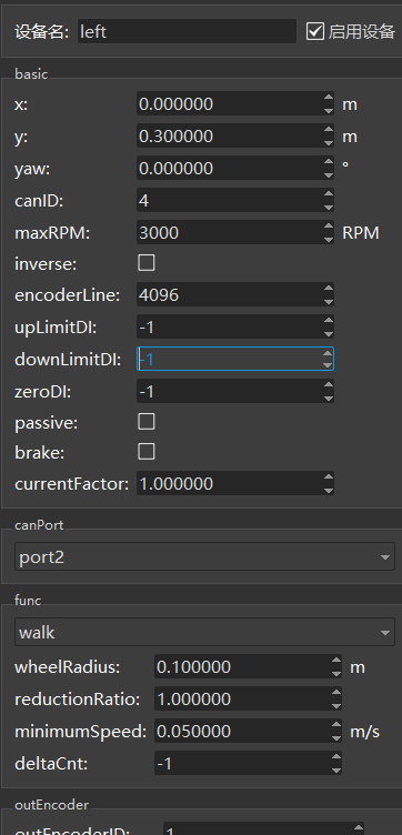
5. Robot Model Configuration Instructions
The parameters of the walking motor are configured based on the actual conditions of the motor and deceleration. The brand is ELMO-CANOpen.
Note: These parameters should be filled in according to the actual conditions of the driver, motor, and reducer selected;
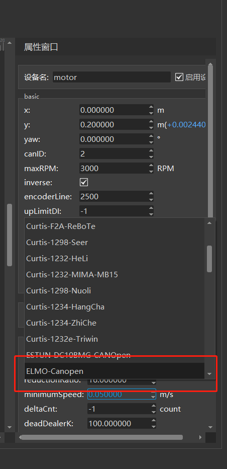
****
Note: The deceleration ratio, number of encoder lines, maximum motor speed, and driver brand should be filled in according to the actual selection.
Six, Drive Function Detection
1. Prior to installing the shell after vehicle assembly, double-check the cables to ensure proper connection.
2. Elevate the car body to raise the wheels off the ground. Activate the robot and connect it to a network cable. Utilize Roboshop software to control the robot and set the wheels in motion. Employ the CanScope clip to detect CAN messages on the CAN bus for a minimum of 1 hour. The CAN messages are devoid of errors.
Step 3: Place the car body on the ground and utilize the Roboshop software to control the robot's movements, including forward, backward, left, and right.
4. Prior to pressing the emergency stop button, attempt to push the robot. If it does not move (motor is disabled), verify that the Roboshop robot is in the "No Emergency Stop" and "Drive No Emergency Stop" state, as depicted in Figure 6.1. Once the emergency stop button has been activated, push the robot again to enable the motor and ensure that it is now in the "Emergency Stop" and "Drive Emergency Stop" state in Roboshop, as illustrated in Figure 6.2.
5. Test the communication between the driver and the controller by using the Roboshop software to operate the robot and move it forward. During the movement process, unplug the canH and canL connections between the driver and the controller.

Figure 6.1:

Figure 6.2:
Perform a 24-hour task chain motion aging test and check the Robokit Log for any error alarms.
Vii. Supplementary Material
7.1 Usage of the USB CAN card
1. Software Installation - Install the USB_CAN Tool software (Contact the CAN card vendor for software and user manuals).
2. Hardware Connection - Acquire a USB CAN card and cables, then connect the CAN_H cable to the SRC2000 external wiring harness TE35 33, and connect the CAN_L cable to the SRC2000 external wiring harness TE35 32. Refer to Figure 7.1.1:

Figure 7.1.1:
3. Open the USB CAN tool, select [Device Operation (O)] and then select [Start Device (S)]. Confirm the CAN parameters, setting the [baud rate] to 250Kbps and selecting [CAN channel number] as channel 1. Finally, click [Confirm]. Refer to Figure 7.1.2 for details.

Figure 7.1.2:
4. Choose "Display (V)" and uncheck "Merge same ID data (M)". The CAN message is displayed in Figure 7.1.3.
 Figure 7.1.3:
7.2 Usage of udpconsole
udpConsole is a handy tool utilized by our engineers for debugging purposes. It allows you to review the error information reported by the firmware.
1. Prior to launching the udpconsole tool, ensure that the computer is physically linked to the robot via a network cable.
2. Launch udpconsole to test the driver functionality and verify the displayed content on udpconsole.
Error frames may occur during driver communication, as illustrated in Figure 7.2.1:

Figure 7.2.1
Figure 7.2.1 - Enhanced visualization of data.
Common Error Codes for Drives
The green LED serves as the power indicator. It remains steady on when the driver is powered on and goes out when the power is cut off. The red LED, on the other hand, acts as the fault indicator. In case of a driver failure, the driver stops and prompts the corresponding fault code. The user can clear the alarm using the software, and the fault can be resolved.


Example: This motor reads errors bit by bit. For instance, 1.0x81 error
can be analyzed by referring to the overvoltage error in the table information.
2.0x8 indicates overload, while 3.8080 refers to voltage error.
9. Appendix
9.1 Driver Wiring Diagram


 Thanks feedback
 Thanks feedback
 Build your own AMR fleet within days


